
TM 5-3805-294-23-4
0653
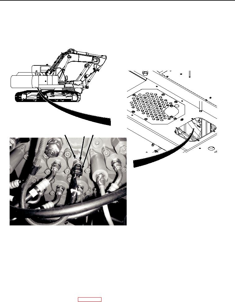
INSTALLATION - Continued
NOTE
Install tie wraps as required.
1.
Lightly lubricate O-ring (Figure 2, Item 3) with clean oil.
4
2, 3
1
HYEX00958
Figure 2. Boom Up Pressure Sensor Installation.
2.
Install O-ring (Figure 2, Item 3) to boom up pressure sensor (Figure 2, Item 2).
3.
Install boom up pressure sensor (Figure 2, Item 2) and O-ring (Figure 2, Item 3) to main control valve (Figure
2, Item 4).
4.
Connect wire harness connector B30 (Figure 2, Item 1) to boom up pressure sensor (Figure 2, Item 2).
END OF TASK
FOLLOW-ON MAINTENANCE:
1.
Connect negative battery cable. (WP 0521)