
TM 5-3805-294-23-4
0653
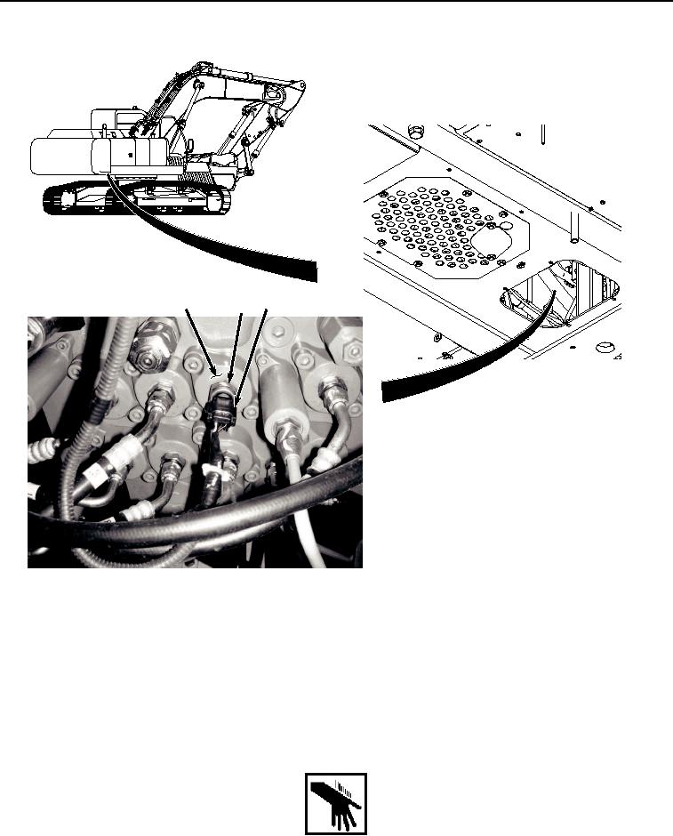
REMOVAL - Continued
4
2, 3
1
HYEX00958
Figure 1. Boom Up Pressure Sensor Removal.
2.
Remove boom up pressure sensor (Figure 1, Item 2) and O-ring (Figure 1, Item 3) from main control valve
(Figure 1, Item 4).
3.
Remove O-ring (Figure 1, Item 3) from boom up pressure sensor (Figure 1, Item 2). Discard O-ring.
END OF TASK
INSTALLATION
WARNING