
TM 5-3805-294-23-4
0657
INSTALLATION - Continued
12.
Install O-ring (Figure 3, Item 8) and O-ring (Figure 3, Item 9) to control valve (Figure 3, Item 7).
13.
Install housing (Figure 3, Item 6) to control valve (Figure 3, Item 7) with four screws (Figure 3, Item 5).
14.
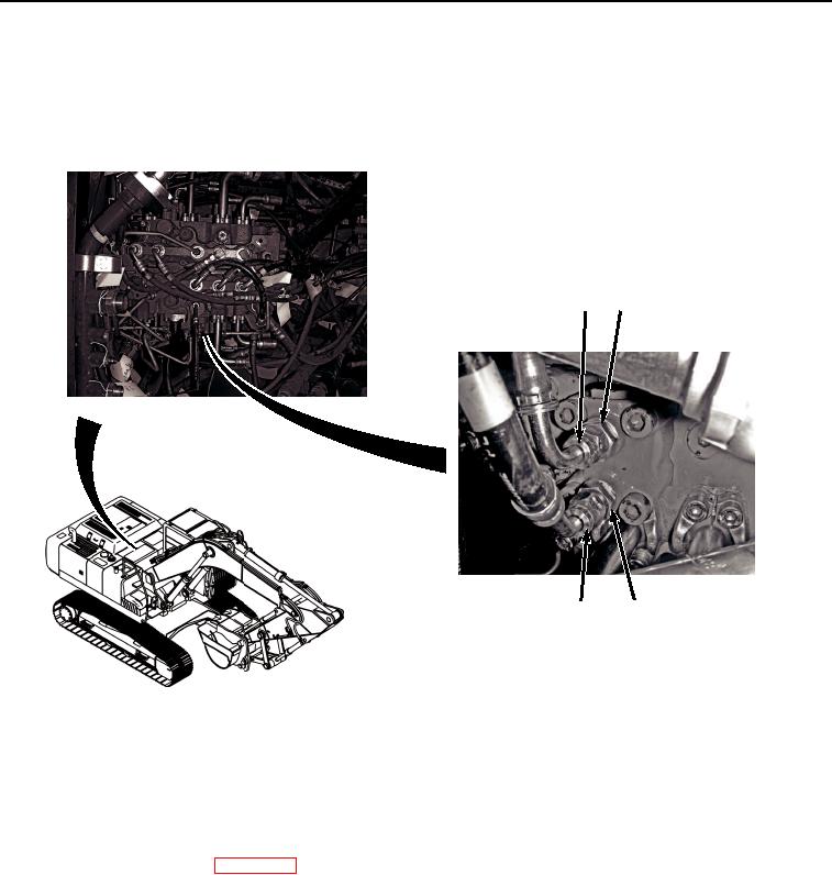
Install hose (Figure 4, Item 3) to fitting (Figure 4, Item 4).
1
2
3
4
HYEX03369
Figure 4.
Hose Installation.
15.
Install hose (Figure 4, Item 1) to fitting (Figure 4, Item 2).
END OF TASK
FOLLOW-ON MAINTENANCE
1.
Install center top cover. (WP 0589)
2.
Perform the Standard Follow-On Maintenance Instructions. (Volume 3, WP 0384)
END OF TASK
END OF WORK PACKAGE