TM 5-2420-230-24-1
.
(7)
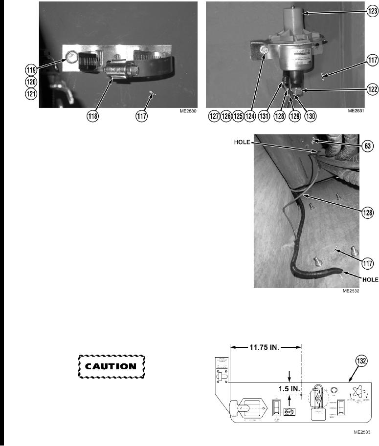
Install cylinder clamp (118) on stowage
box (117) with two screws (119),
lockwashers (120), and nuts (121).
(8)
Install valve fitting (122) on valve
assembly (123).
(9)
Install valve assembly (123) on stowage
box (117) with two screws (124),
washers (125), lockwashers (126), and
nuts (127).
(10) Cover 8.5 ft. wire (128), 9.5 ft. wire (129) and
8 ft. tube (130) with 9.5 ft. wire
sleeving (131).
(11) Route wire (128), wire (129), and tube (130)
through hole in stowage box (117).
(12) Route wire (128) through opening in bottom
of cab (63).
(13) Measure and mark hole position on side
instrument panel (132).
Use care when drilling through side
instrument panel. Ensure drill does not contact
any wires or components. Failure to comply
will result in damage to equipment.
(14) Using a 5/8-in. drill bit, drill hole on side
instrument panel (132).
Change 1
20-14

