
TM 5-2420-230-24-1
Maintenance & Service Manual
R & HR32000 3 & 6 Speed LD
Figure 220
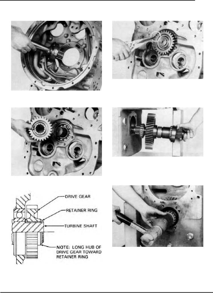
Install drive gear retainer ring.
TRANSMISSION REASSEMBLY
Figure 218
Install turbine shaft and bearing in converter housing.
SEE 6 SPEED SECTION FOR RANGE SHIFT OUTPUT
SHAFT INSTALLATION.
Figure 221
View of output shaft as it would be positioned in transmission
case. NOTE: Front cone bearing shouldered on shaft with large
diameter of bearing in, and long hub of gear toward gear spacer.
Figure 219
Install turbine shaft drive gear as shown in Figure 219-A.
Figure 222
Position output gear in transmission case with protruding hub
toward front of case. See FIgure 221. Insert output shaft, gear
spacer and taper bearing from front of case and through output
gear. Install front taper bearing cup. Block output shaft and in-
stall rear taper bearing with large diameter in.
Figure 219-A
--38--