
TM 5-2420-230-24-1
Maintenance & Service Manual
R & HR32000 3 & 6 Speed LD
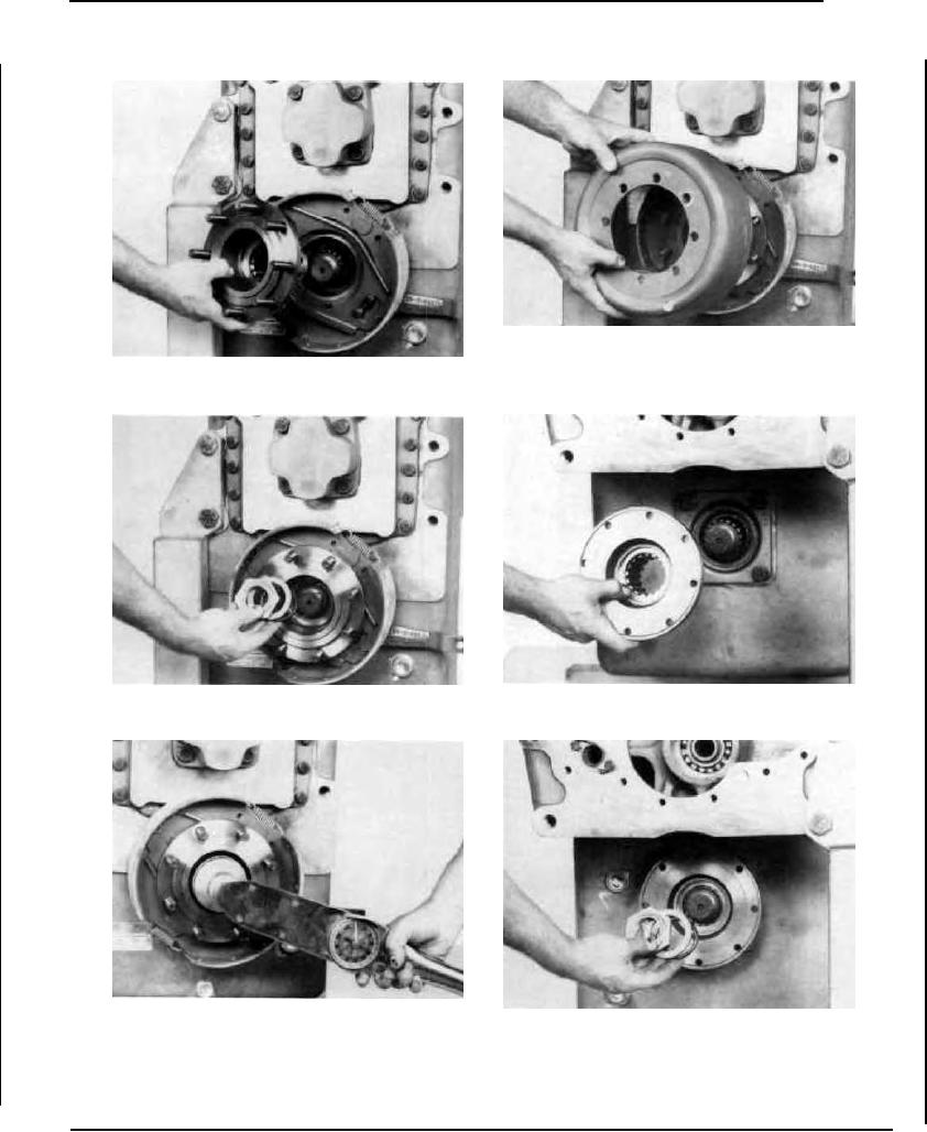
Figure 256
Position brake drum on output flange studs. Install stud nut
washers and stud nuts. Tighten stud nuts enough to hold drum
Figure 253
in place until drive shaft is installed.
Install rear output flange.
Figure 254
Figure 257
Install flange "O" ring, washer adn lock nut.
Install front output flange.
Figure 255
Figure 258
Tighten lock nut to specified torque. (See elastic stop nut torque
chart).
Install new output flange "O" ring, washer and flange nut.
--44--
F-89