
TM 5-2420-230-24-1
Maintenance & Service Manual
R & HR32000 3 & 6 Speed LD
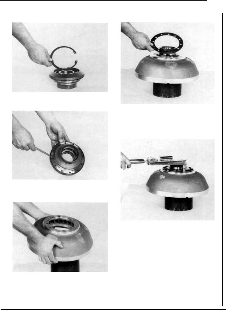
Figure 283
Install bearing retainer ring.
Figure 286
Position backing ring on impeller.
Figure 284
Position new "O" ring on impeller hub.
Figure 287
Install (12) impeller hub special screws to approximately .06
inch (1,5) of seated position. With a calibrated torque wrench,
tighten screws to 40-45 lbs. ft. [54,3-61.0 N.m.] torque. NOTE:
Assembly of impeller to impeller hub must be completed within
a fifteen minute period from start of screw installation. The
screws are prepared with a coating which begins to harden after
installation in the impeller hub holes. If not tightened to proper
torque within the fifteen minute period, insufficient screw
clamping tension will result. The special screw is to be used for
one installation only. If the screw is removed for any reason it
must be replace.
The compound left in the hub holes must be removed with the
proper tap and cleaned with solvent. Dry hole thoroughly and
Figure 285
use a new screw for reinstallation.
Align holes in impeller with holes in impeller hub.
--49--
F-94