
TM 5-2420-230-24-1
Maintenance & Service Manual
R & HR32000 3 & 6 Speed LD
Figure 305
Figure 308
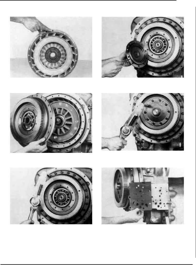
Position a new "O" ring on impeller cover.
Position new "O" ring on impeller cover bearing cap.
Figure 309
Figure 306
Install bearing cap, bolts and washers, tighten to specified
Position turbine and impeller cover on turbine shaft.
torque. (See torque chart).
Figure 310
Figure 307
Install aligning studs to facilitate control valve assembly. Install
Install impeller cover to impeller bolts and washers. Tighten to
new control valve gasket.
specified torque (see torque chart).
--53--
F-98