
TM 5-2420-230-24-1
Maintenance & Service Manual
R & HR32000 3 & 6 Speed LD
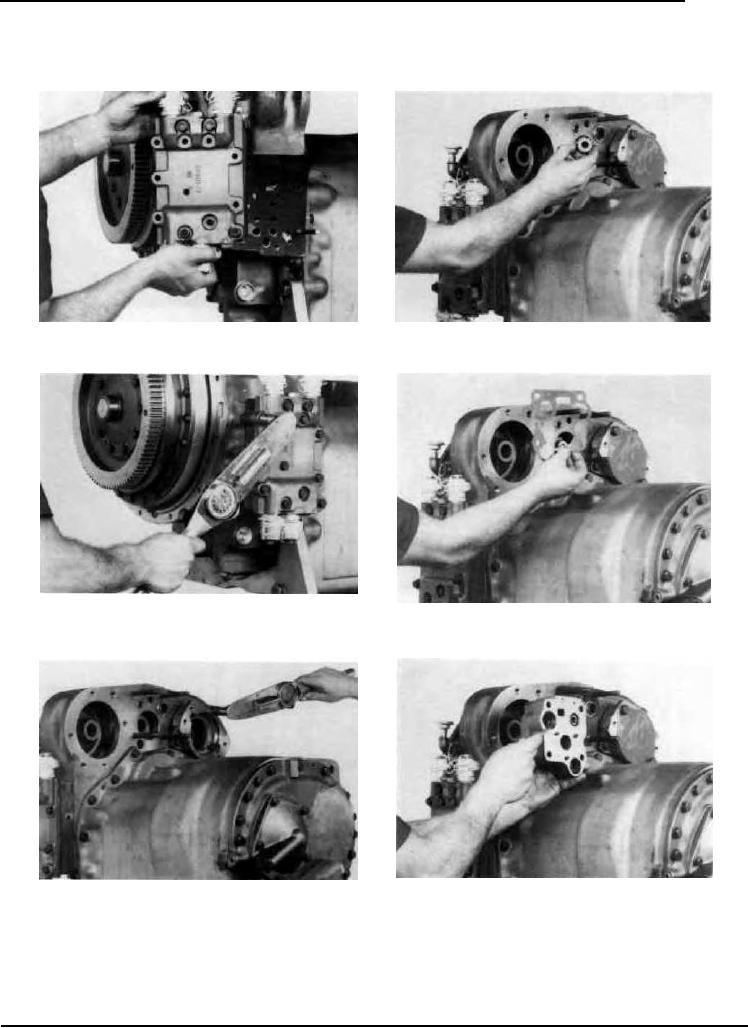
Figure 311
Figure 314
Position control valve assembly on aligning studs.
Install charging pump drive sleeve.
Figure 312
Install control valve bolts and washers and tighten to specified
Figure 315
torque. (See torque chart).
Install new pressure regulating valve gasket.
Figure 316
Figure 313
Install new "O" rings on pressure regulating valve. Position
Install pump adaptor, bolts and washers. Tighten to specified
valve on studs.
torque. (See torque chart).
--54--
F-99