
TM 5-2420-230-24-1
Maintenance & Service Manual
R & HR32000 3 & 6 Speed LD
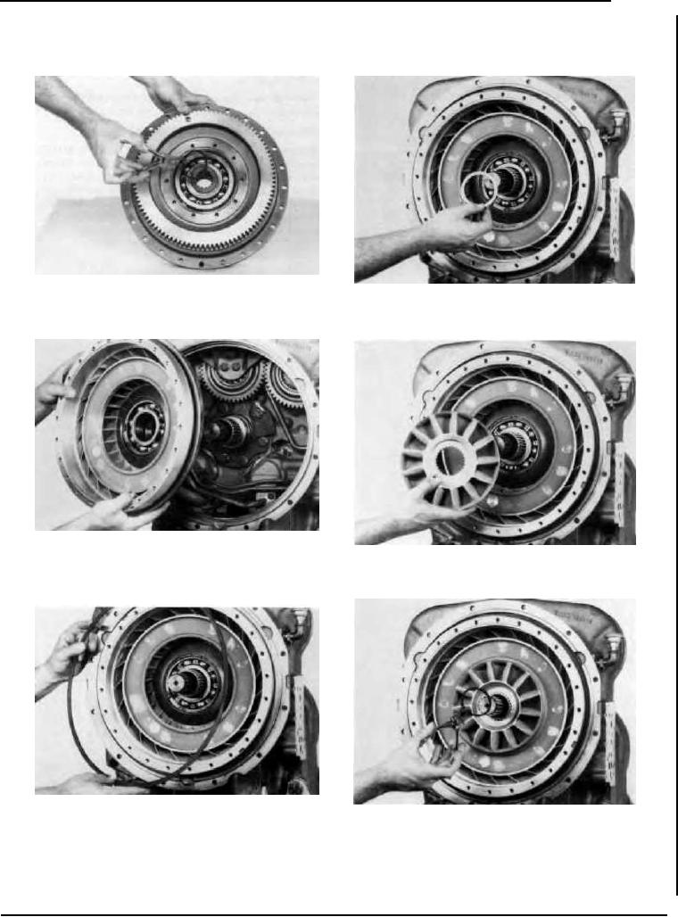
Figure 299
Install turbine hub to impeller cover retainer ring.
Figure 302
Install reaction member spacer with tang facing out.
Figure 300
Grease stator support piston ring, oil baffle oil seal and seal ring
Figure 303
to facilitate reassembly. Install impeller and oil baffle assembly
Install reaction member with thick part of blades out.
in converter housing.
Figure 301
Position oil baffle in housing. Secure with oil baffle retainer ring,
Figure 304
being sure ring is in full position in ring groove.
Install reaction member retainer ring.
--52--
F-97