TM 5-3805-280-24-2
Cylinder Block, Liners, Pistons and Rods
10
INSTALLING PISTON PIN BUSHING IN STRAIGHT
39
PIN-END ROD
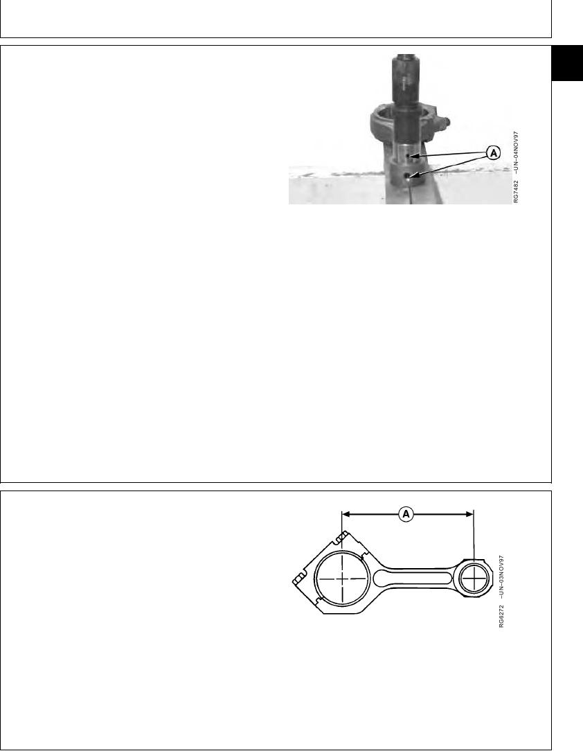
IMPORTANT: Oil holes (A) MUST be aligned. If holes
are not aligned, remove and discard
bushing. Install a new bushing. DO NOT
attempt to reuse the bushing. Install
bushing in rod.
1. Use JD286 Driver for 41 mm (1.6 in.) pin or JDE88
Driver for 35 mm (1.3 in.) pin to install bushing.
2. Press bushing into rod bore until edge of bushing is
A--Oil Holes
flush or just slightly below machined surface on face of
rod.
3. Remove rod from press.
4. I.D. of new bushing must be precision bored by
specialized machine shop to specifications.
Connecting Rod Pin-to-Bushing (Straight Pin-End)--Specification
Oil Clearance................................................................ 0.020 --0.056 mm
(0.0008--0.0022 in.)
Wear Limit .............................................................. 0.102 mm (0.0040 in.)
RG,10,DT7404 1912NOV972/2
MEASURE ROD CENTER-TO-CENTER
BORES
Measure rod center-to-center bores (A) (with bushings
removed). Compare to specifications given below.
Replace rod if necessary.
Rod Bearing Bore-to-Piston Pin Bushing Bore (Center-to-Center)--
Specification
Measurement............................................................. 202.95--203.05 mm
(7.990--7.994 in.)
A--Center-to Center Measurement
RG,10,DT7403 1912NOV971/1
13-152

