
TM 5-3805-294-23-4
0494
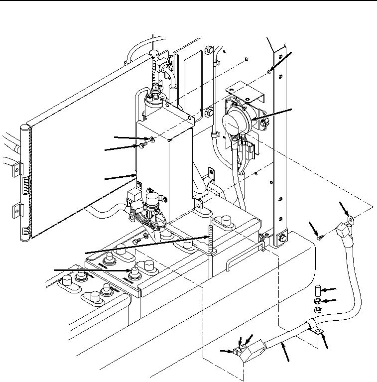
REMOVAL
35
39
33
32
34
37
36
4
28
29
30
27 25
26
31
38
HYEX00193
Figure 4. Battery Relay Cover and Positive Battery Cable Removal.
11.
Remove positive battery terminal clamp (Figure 4, Item 27) from positive battery terminal (Figure 4, Item 28).
12.
Remove spacer (Figure 4, Item 29), two nuts (Figure 4, Item 30), and clamp (Figure 4, Item 31) from bolt (Figure
4, Item 4).
13.
Remove three screws (Figure 4, Item 32), washers (Figure 4, Item 33), and cover (Figure 4, Item 34) from
panel (Figure 4, Item 35).
14.
Place cover (Figure 4, Item 35) and attached wires to side.