
TM 5-3805-294-23-4
0494
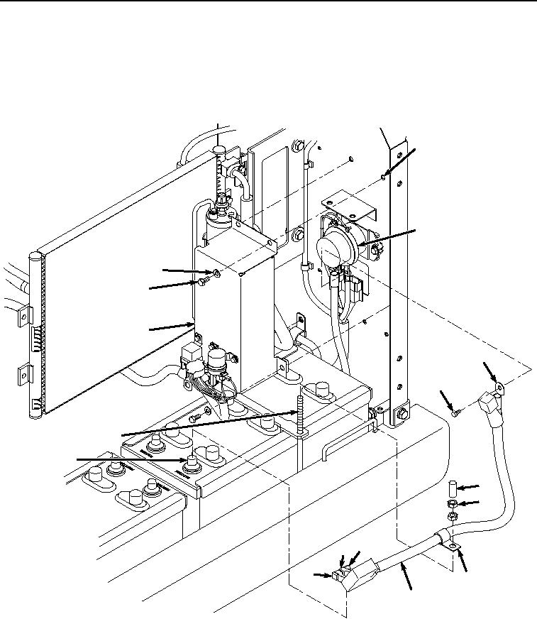
INSTALLATION - Continued
NOTE
Install tie wraps as required.
1.
Install positive battery cable (Figure 5, Item 38) and terminal (Figure 5, Item 37) to relay (Figure 5, Item 39)
with screw (Figure 5, Item 36).
35
39
33
32
34
37
36
4
28
29
30
27 25
26
31
38
HYEX00193
Figure 5. Positive Battery Cable and Battery Relay Cover Installation.
2.
Install cover (Figure 5, Item 34) to panel (Figure 5, Item 35) with three washers (Figure 5, Item 33) and screws
(Figure 5, Item 32).
3.
Install clamp (Figure 5, Item 31), two nuts (Figure 5, Item 30), and spacer (Figure 5, Item 29) to bolt (Figure 5,
Item 4).