
TM 5-3805-294-23-4
0495
REMOVAL - Continued
4
3
11
2
17
1
14
16
13
12
9
8
15
7
13
6
5
10
6
5
HYEX00299
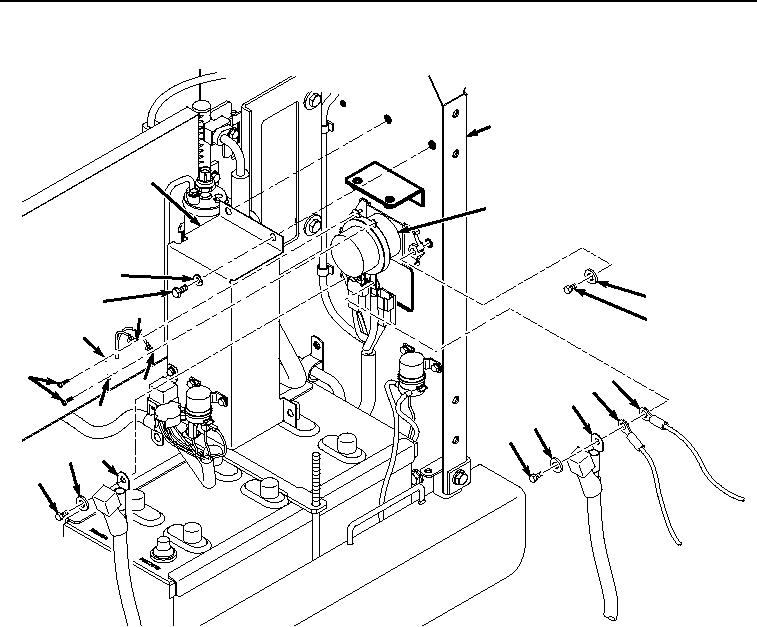
Figure 1. Battery Relay Removal.
2.
Remove two screws (Figure 1, Item 5), washers (Figure 1, Item 6), battery positive cable (Figure 1, Item 7),
coolant heater wiring harness connector (Figure 1, Item 8), glow plug wiring harness connector (Figure 1, Item
9), and starter positive cable (Figure 1, Item 10) terminals from bottom of battery relay K19 (Figure 1, Item 11).
3.
Remove two screws (Figure 1, Item 12), washers (Figure 1, Item 13), battery wiring harness (Figure 1, Item
14), and battery wiring harness (Figure 1, Item 15) terminals from top of battery relay K19 (Figure 1, Item 11).
4.
Remove two screws (Figure 1, Item 16), washers (Figure 1, Item 17), and battery relay K19 (Figure 1, Item
11) from frame (Figure 1, Item 4).
END OF TASK