
TM 5-3805-294-23-4
0508
REMOVAL - Continued
8
6
5
9
10
1
7
11
3
6
5
4
2
11
6
5
HYEX00302
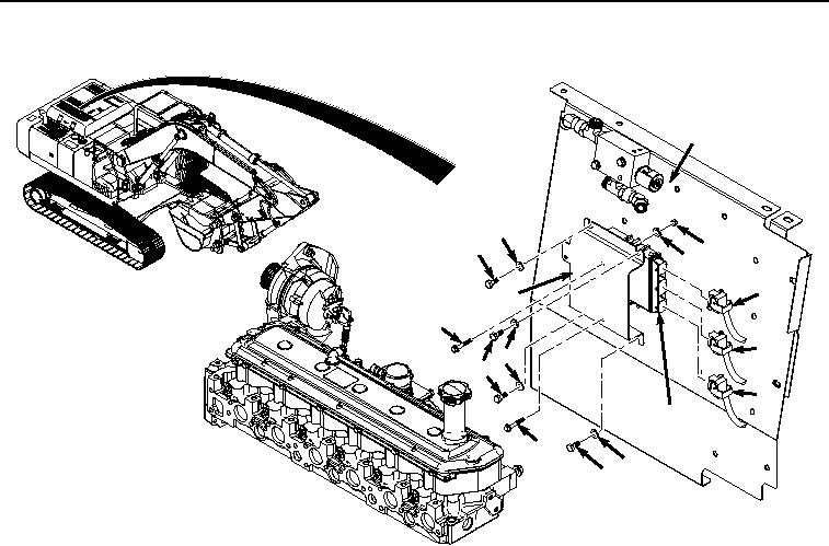
Figure 1.
Engine Control Unit Removal.
2.
Disconnect wiring harness connector J02 (Figure 1, Item 3) from ECU (Figure 1, Item 2).
3.
Disconnect wiring harness connector J03 (Figure 1, Item 4) from ECU (Figure 1, Item 2).
4.
Remove four bolts (Figure 1, Item 5), washers (Figure 1, Item 6), and bracket (Figure 1, Item 7) from cover
(Figure 1, Item 8).
5.
Remove two nuts (Figure 1, Item 9), washers (Figure 1, Item 10), bolts (Figure 1, Item 11), and ECU (Figure
1, Item 2) from bracket (Figure 1, Item 7).
END OF TASK
INSTALLATION
1.
Install ECU (Figure 2, Item 2) to bracket (Figure 2, Item 7) with two bolts (Figure 2, Item 11), washers (Figure
2, Item 10), and nuts (Figure 2, Item 9).