
TM 5-3805-294-23-4
0508
INSTALLATION - Continued
8
6
5
9
10
1
7
11
3
6
5
4
2
11
6
5
HYEX00302
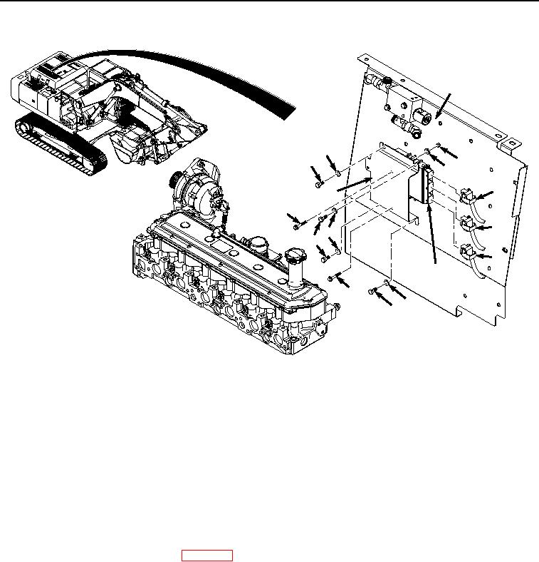
Figure 2.
Engine Control Unit Installation.
2.
Install bracket (Figure 2, Item 7) to cover (Figure 2, Item 8) with four washers (Figure 2, Item 6) and bolts
(Figure 2, Item 5).
3.
Connect wiring harness connector J03 (Figure 2, Item 4) to ECU (Figure 2, Item 2).
4.
Connect wiring harness connector J02 (Figure 2, Item 3) to ECU (Figure 2, Item 2).
5.
Connect wiring harness connector J01 (Figure 2, Item 1) to ECU (Figure 2, Item 2).
END OF TASK
FOLLOW-ON MAINTENANCE:
1.
Connect negative battery cable. (WP 0521)
2.
Perform the Standard Follow-On Maintenance Instructions. (Volume 3, WP 0384)
END OF TASK
END OF WORK PACKAGE