
TM 5-3805-294-23-4
0509
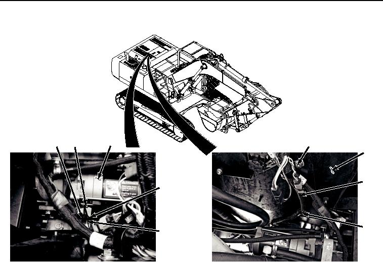
REMOVAL - Continued
39
29
40
33
30
34
41
4
38
32
35
31
36
37
HYEX03163
Figure 4. Engine Interface Wiring Harness From Starter Removal.
13.
Remove three bolts (Figure 4, Item 35), washers (Figure 4, Item 36), and clamps (Figure 4, Item 37) from
machine (Figure 4, Item 4).
14.
Remove clamp (Figure 4, Item 37) from engine interface wiring harness (Figure 4, Item 38).
15.
Remove bolt (Figure 4, Item 39), washer (Figure 4, Item 40), and clamp (Figure 4, Item 41) from machine
(Figure 4, Item 4).
16.
Remove clamp (Figure 4, Item 41) from engine interface wiring harness (Figure 4, Item 38).
17.
Disconnect engine interface wiring harness connector R0 (Figure 5, Item 42) from glow plug wiring connector
(Figure 5, Item 43).