
TM 5-3805-294-23-4
0509
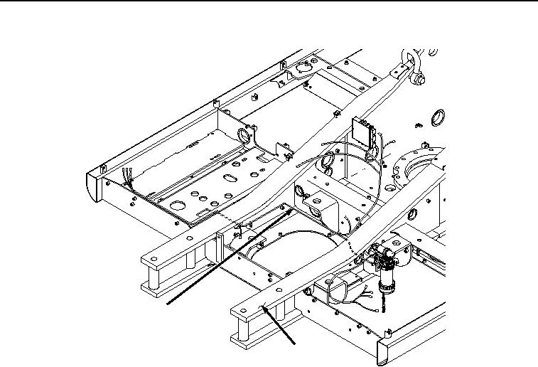
REMOVAL - Continued
38
4
HYEX03166
Figure 8. Engine Interface Wiring Harness From Machine Removal.
END OF TASK
INSTALLATION
NOTE
Space in frame access is limited. Use twine attached to engine interface wiring harness during
removal to aid in routing of cable during installation.
1.
Install engine interface wiring harness (Figure 9, Item 38) to machine (Figure 9, Item 4).