
TM 5-3805-294-23-4
0509
INSTALLATION - Continued
39
29
40
33
30
34
41
4
38
32
35
31
36
37
HYEX03163
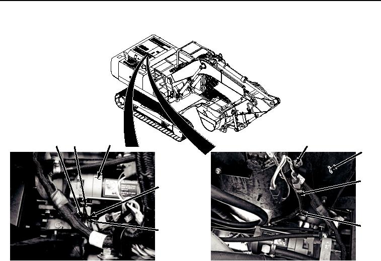
Figure 13. Engine Interface Wiring Harness To Starter Installation.
16.
Install clamp (Figure 13, Item 41) and engine interface wiring harness (Figure 13, Item 38) to machine (Figure
13, Item 4) with bolt (Figure 13, Item 39) and washer (Figure 13, Item 40).
17.
Install clamp (Figure 13, Item 37) to engine interface wiring harness (Figure 13, Item 38).
18.
Install three clamps (Figure 13, Item 37) and engine interface wiring harness (Figure 13, Item 38) to machine
(Figure 13, Item 4) with three bolts (Figure 13, Item 35) and washers (Figure 13, Item 36).
19.
Install ground strap (Figure 13, Item 33), ground wire (Figure 13, Item 32), and engine interface wiring harness
ground wire (Figure 13, Item 31) to starter (Figure 13, Item 34) with nut (Figure 13, Item 29) and lockwasher
(Figure 13, Item 30).
20.
Connect engine interface wiring harness connector E1 (Figure 14, Item 27) to starter protection wiring harness
connector (Figure 14, Item 28).