
TM 5-3805-294-23-4
0509
INSTALLATION - Continued
52
53
55
54
56
38
57
4
4
38
HYEX03164
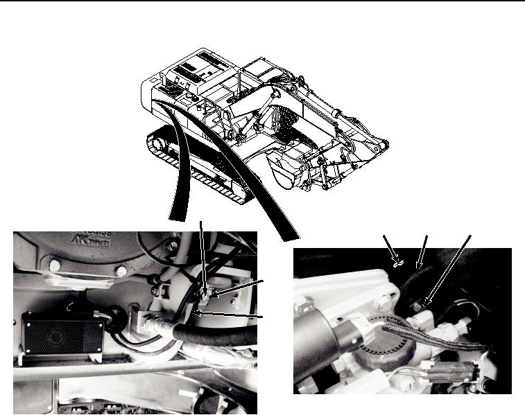
Figure 11.
Engine Interface Wiring Harness Clamps Installation.
7.
Install clamp (Figure 11, Item 57) and engine interface wiring harness (Figure 11, Item 38) to machine (Figure
11, Item 4) with screw (Figure 11, Item 55) and washer (Figure 11, Item 56).
8.
Install clamp (Figure 11, Item 57) to engine interface wiring harness (Figure 11, Item 38).
9.
Install clamp (Figure 11, Item 54) and engine interface wiring harness (Figure 11, Item 38) to machine (Figure
11, Item 4) with screw (Figure 11, Item 52) and washer (Figure 11, Item 53).
10.
Connect engine interface wiring harness connector J02 (Figure 12, Item 50) to ECU connector (Figure 12, Item
51).