
TM 5-3805-294-23-4
0509
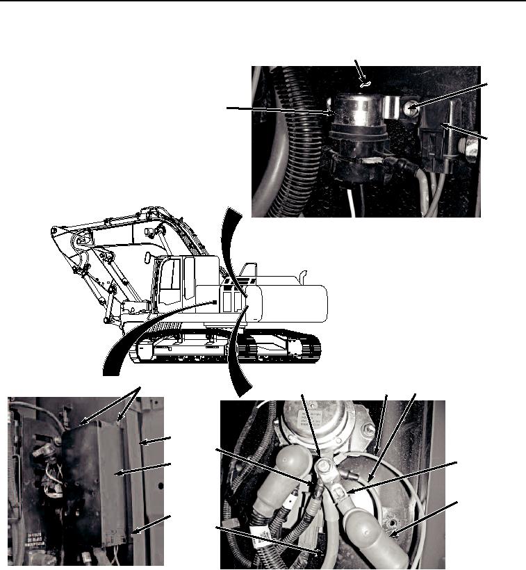
INSTALLATION - Continued
4
13, 14
15
16
1, 2
5, 7
11
10
4
9
8
3
6
1, 2
12
HYEX03156
Figure 16. Engine Interface Wiring Harness To Battery Relay Installation.
27.
Install slave receptacle positive cable (Figure 16, Item 12), coolant heater fuse holder connector (Figure 16,
Item 11), glow plug fuse holder wire connector (Figure 16, Item 10), machine wiring harness connector (Figure
16, Item 9), and battery positive cable (Figure 16, Item 8) to battery relay terminal (Figure 16, Item 5) with bolt
(Figure 16, Item 7).
28.
Move protective boot (Figure 16, Item 6) over battery relay terminal (Figure 16, Item 5).