
TM 5-3805-294-23-4
0510
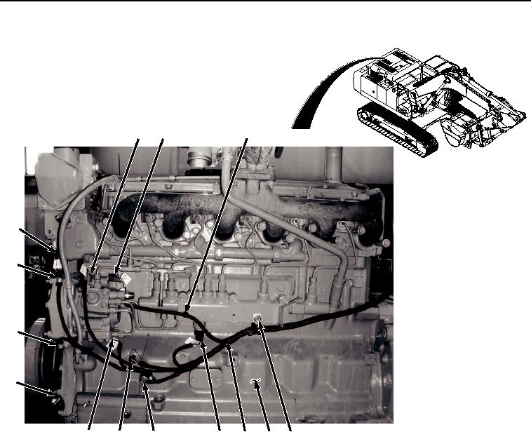
REMOVAL - Continued
11
13
12
14
21
1
2
3
4
9
10
7
8
15
17
22
19
5
6
23
16
18
20
HYEX03193
Figure 1. Engine Left Side Wiring Harness Removal.
2.
Remove nut (Figure 1, Item 3), bolt and clamp assembly (Figure 1, Item 4), and engine wiring harness (Figure
1, Item 5) from engine (Figure 1, Item 6).
3.
Disconnect engine wiring harness connector X01 (Figure 1, Item 7) from crankshaft position sensor (Figure 1,
Item 8).
4.
Remove nut (Figure 1, Item 9), screw and clamp assembly (Figure 1, Item 10), and engine wiring harness
(Figure 1, Item 5) from engine (Figure 1, Item 6).
5.
Disconnect engine wiring harness connector T05 (Figure 1, Item 11) from fuel temperature sensor (Figure 1,
Item 12).
6.
Disconnect engine wiring harness connector Y01 (Figure 1, Item 13) from pump control valve (Figure 1, Item
14).
7.
Disconnect engine wiring harness connector X02 (Figure 1, Item 15) from engine position sensor (Figure 1,
Item 16).
8.
Disconnect engine wiring harness connector P04 (Figure 1, Item 17) from oil pressure sensor (Figure 1, Item
18).