
TM 5-3805-294-23-4
0510
REMOVAL - Continued
9.
Disconnect engine wiring harness connector P05 (Figure 1, Item 19) from rail pressure sensor (Figure 1, Item
20).
NOTE
Tie wrap assembly is part of the engine wiring harness assembly.
10.
Remove tie wrap assembly (Figure 1, Item 21) and engine wiring harness (Figure 1, Item 5) from engine (Figure
1, Item 6).
11.
Remove bolt and clamp assembly (Figure 1, Item 22) and engine wiring harness (Figure 1, Item 5) from engine
(Figure 1, Item 6).
12.
Remove bolt and clamp assembly (Figure 1, Item 23) from engine (Figure 1, Item 6).
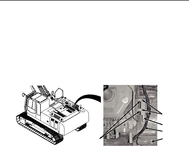
13.
Remove two screws (Figure 2, Item 24), bracket (Figure 2, Item 25), engine wiring harness (Figure 2, Item 5),
and two spacers (Figure 2, Item 26) from engine (Figure 2, Item 6).
24
25
5
6
26
HYEX03645
Figure 2. Bracket Removal.
14.
Disconnect engine wiring harness connector T06 (Figure 3, Item 27) from compressor inlet temperature sensor
(Figure 3, Item 28).