
TM 5-3805-294-23-4
0514
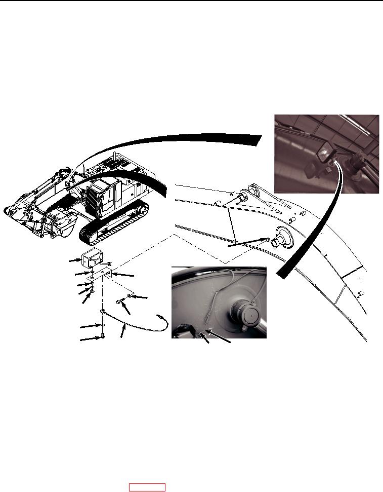
INSTALLATION - Continued
tools can catch on equipment, contact positive electrical circuits, and cause a direct short,
severe burns, or electrical shock. Failure to comply may result in injury or death to personnel.
NOTE
Install tie wraps as required.
1.
Install angle mounting bracket (Figure 2, Item 6) to block (Figure 2, Item 14) with screw (Figure 2, Item 12) and
washer (Figure 2, Item 13).
14
10
11
6
9
8
13
7
12
4
3
5
HYEX02172
2
1
Figure 2. Left Boom Work Light Installation.
2.
Install light (Figure 2, Item 10) to angle mounting bracket (Figure 2, Item 6) with washer (Figure 2, Item 11),
washer (Figure 2, Item 9), washer (Figure 2, Item 8), and nut (Figure 2, Item 7).
3.
Install screw (Figure 2, Item 3), washer (Figure 2, Item 4), and wire harness (Figure 2, Item 5) on angle mounting
bracket (Figure 2, Item 6).
4.
Connect left boom work light electrical terminal (Figure 2, Item 1) to work light wiring harness E4 (Figure 2,
Item 2).
END OF TASK
FOLLOW-ON MAINTENANCE
1.
Connect negative battery cable. (WP 0521)