
TM 5-3805-294-23-4
0513
INSTALLATION - Continued
1
2
4
5
7
6
HYEX00319
3
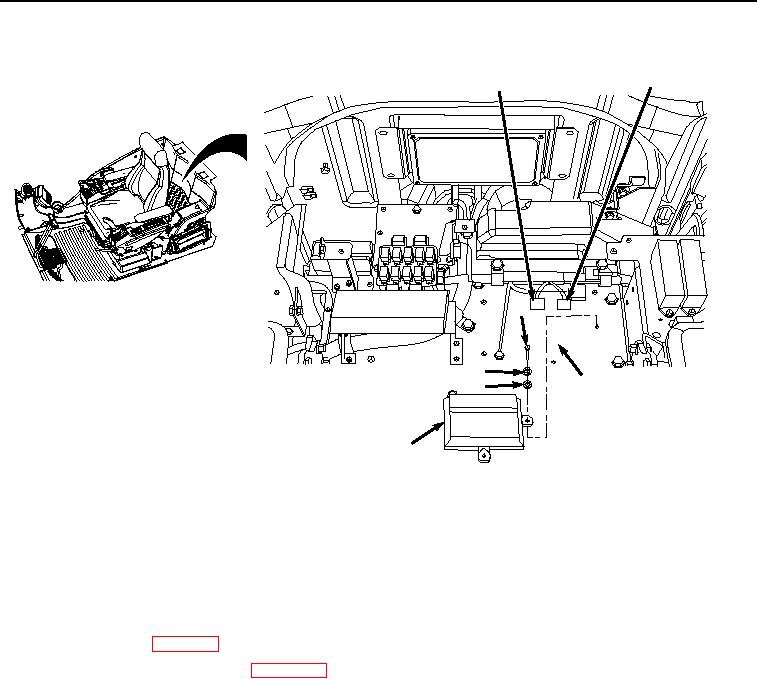
Figure 2.
Connectors Installation.
2.
Connect cab wiring harness W1 connectors X34 (Figure 2, Item 2) and X32 (Figure 2, Item 1) to information
controller (Figure 2, Item 3).
END OF TASK
FOLLOW-ON MAINTENANCE
1.
Install rear tray. (WP 0566)
2.
Connect negative battery cable. (WP 0521)
3.
Perform the Standard Follow-On Maintenance Instructions. (Volume 3, WP 0384)
END OF TASK
END OF WORK PACKAGE