
TM 5-3805-294-23-4
0512
INSTALLATION - Continued
3
2
1
10
4
20
15
9
5
19
7
14
8
18
6
17
13
16
12
11
HYEX00744
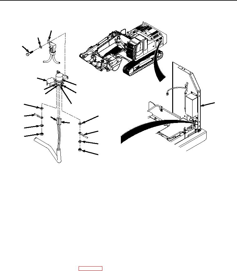
Figure 2. Glow Plug Relay Installation.
2.
Install engine interface wiring harness connector (Figure 2, Item 13) to glow plug relay terminal (Figure 2, Item
15) with washer (Figure 2, Item 14), lockwasher (Figure 2, Item 12), and nut (Figure 2, Item 11).
3.
Close cover (Figure 2, Item 10) on glow plug relay (Figure 2, Item 4).
4.
Connect engine interface wiring harness connector (Figure 2, Item 8) to glow plug relay terminal (Figure 2,
Item 9).
5.
Connect engine interface wiring harness connector (Figure 2, Item 6) to glow plug relay terminal (Figure 2,
Item 7).
6.
Install glow plug relay (Figure 2, Item 4) and coolant heater fuse holder (Figure 2, Item 3) to frame (Figure 2,
Item 5) with two washers (Figure 2, Item 2) and bolts (Figure 2, Item 1).
END OF TASK
FOLLOW-ON MAINTENANCE
1.
Connect negative battery cable. (WP 0521)
2.
Perform the Standard Follow-On Maintenance Instructions. (Volume 3, WP 0384)
END OF TASK
END OF WORK PACKAGE