
TM 5-3805-294-23-4
0511
RELAY CONNECTOR REPAIR - Continued
CAUTION
Extractor tool is fragile. Use gentle force when inserting tool. Do not force tool further into
connector body after a positive stop is felt. If wire does not release, remove tool and try again.
Failure to comply may result in damage to equipment.
NOTE
Tag and mark wires, connectors, and wiring harnesses prior to removal to ensure proper
installation.
Note position of each tie wrap and remove as required.
1.
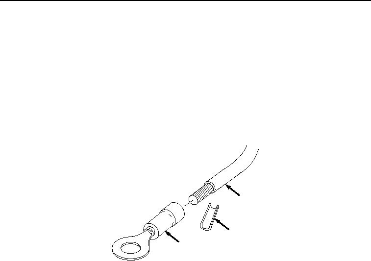
Cut and remove terminal (Figure 18, Item 59) from wire (Figure 18, Item 60).
60
61
59
HYEX03224
Figure 18. Relay Connector Repair.
2.
Remove 1/4 in. (6 mm) of insulation (Figure 18, Item 61) from end of wire (Figure 18, Item 60).
NOTE
Ensure all strands of wire are inside terminal when installing.
3.
Install wire (Figure 18, Item 60) to terminal (Figure 18, Item 59) and crimp.
END OF TASK
END OF WORK PACKAGE