
TM 5-3805-294-23-4
0511
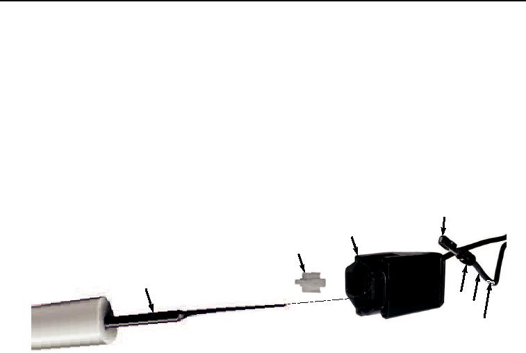
SUMITOMO STYLE CONNECTOR REPAIR - Continued
CAUTION
Extractor tool is fragile. Use gentle force when inserting tool. Do not force tool further into
connector body after a positive stop is felt. If wire does not release, remove tool and try again.
Failure to comply may result in damage to equipment.
NOTE
Tag and mark wires, connectors, and wiring harnesses prior to removal to ensure proper
installation.
Note position of each tie wrap and remove as required.
1.
Remove connector lock (Figure 15, Item 41) from connector (Figure 15, Item 42).
46
42
41
43
45
47
44
HYEX03221
Figure 15. Sumitomo Style Connector Repair.
2.
Insert extractor tool (Figure 15, Item 43) into front of connector (Figure 15, Item 42).
3.
Remove extractor tool (Figure 15, Item 43) and pull wire (Figure 15, Item 44), seal (Figure 15, Item 45), and
terminal (Figure 15, Item 46) from the rear of connector (Figure 15, Item 42) at the same time.
4.
Cut and remove terminal (Figure 15, Item 46) from wire (Figure 15, Item 44).
5.
Remove 1/4 in. (6 mm) of insulation (Figure 15, Item 47) from end of wire (Figure 15, Item 44).
6.
Install seal (Figure 15, Item 45) over insulation (Figure 15, Item 47) and align the two ends.
NOTE
Ensure all strands of wire are inside terminal when installing.
7.
Install wire (Figure 15, Item 44) and seal (Figure 15, Item 45) to terminal (Figure 15, Item 46) and crimp.
NOTE
Terminal will seat only one way. If terminal does not pull into the connector body socket, check
to make sure terminal is aligned correctly.
8.
Insert terminal (Figure 15, Item 46), seal (Figure 15, Item 45), and wire (Figure 15, Item 44) into connector
(Figure 15, Item 42) and push until terminal (Figure 15, Item 46) stops.
9.
Pull on wire (Figure 15, Item 44) to confirm that terminal (Figure 15, Item 46) is locked in connector (Figure
15, Item 42).