
TM 5-3805-294-23-4
0511
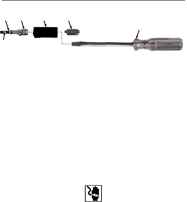
BLADE STYLE WITH LOCK CONNECTOR REPAIR - Continued
57
54
58
53
55
56
HYEX03223
Figure 17. Blade Style With Lock Connector Repair.
2.
Insert screwdriver (Figure 17, Item 55) into front of connector (Figure 17, Item 54).
3.
Remove screwdriver (Figure 17, Item 55) and pull wire (Figure 17, Item 56) and terminal (Figure 17, Item 57)
from the rear of connector (Figure 17, Item 54) at the same time.
4.
Cut and remove terminal (Figure 17, Item 57) from wire (Figure 17, Item 56).
5.
Remove 1/4 in. (6 mm) of insulation (Figure 17, Item 58) from end of wire (Figure 17, Item 56).
NOTE
Ensure all strands of wire are inside terminal when installing.
6.
Install wire (Figure 17, Item 56) to terminal (Figure 17, Item 57) and crimp.
NOTE
Terminal will seat only one way. If terminal does not push into the connector body socket,
check to make sure terminal is aligned correctly.
7.
Insert terminal (Figure 17, Item 57) and wire (Figure 17, Item 56) into connector (Figure 17, Item 54) and push
until terminal (Figure 17, Item 57) stops.
8.
Pull on wire (Figure 17, Item 56) to confirm that terminal (Figure 17, Item 57) is locked in connector (Figure
17, Item 54).
END OF TASK
RELAY CONNECTOR REPAIR
WARNING
Ensure electrical power is off prior to working on all electrical connections. Prior to working
on or around vehicle, remove all jewelry, such as rings, ID tags, bracelets, etc. Jewelry, and
tools can catch on equipment, contact positive electrical circuits, and cause a direct short,
severe burns, or electrical shock. Failure to comply may result in injury or death to personnel.
CAUTION
Terminals come in different styles and sizes. Use only exact replacement. Do not attempt to
modify terminal to fit. Failure to comply may cause damage to component.