
TM 5-3805-294-23-4
0511
SUMITOMO STYLE CONNECTOR REPAIR - Continued
10.
Install connector lock (Figure 15, Item 41) to connector (Figure 15, Item 42).
END OF TASK
BLADE STYLE CONNECTOR REPAIR
WARNING
Ensure electrical power is off prior to working on all electrical connections. Prior to working
on or around vehicle, remove all jewelry, such as rings, ID tags, bracelets, etc. Jewelry, and
tools can catch on equipment, contact positive electrical circuits, and cause a direct short,
severe burns, or electrical shock. Failure to comply may result in injury or death to personnel.
CAUTION
Terminals come in different styles and sizes. Use only exact replacement. Do not attempt to
modify terminal to fit. Failure to comply may cause damage to component.
NOTE
Tag and mark wires, connectors, and wiring harnesses prior to removal to ensure proper
installation.
Note position of each tie wrap and remove as required.
1.
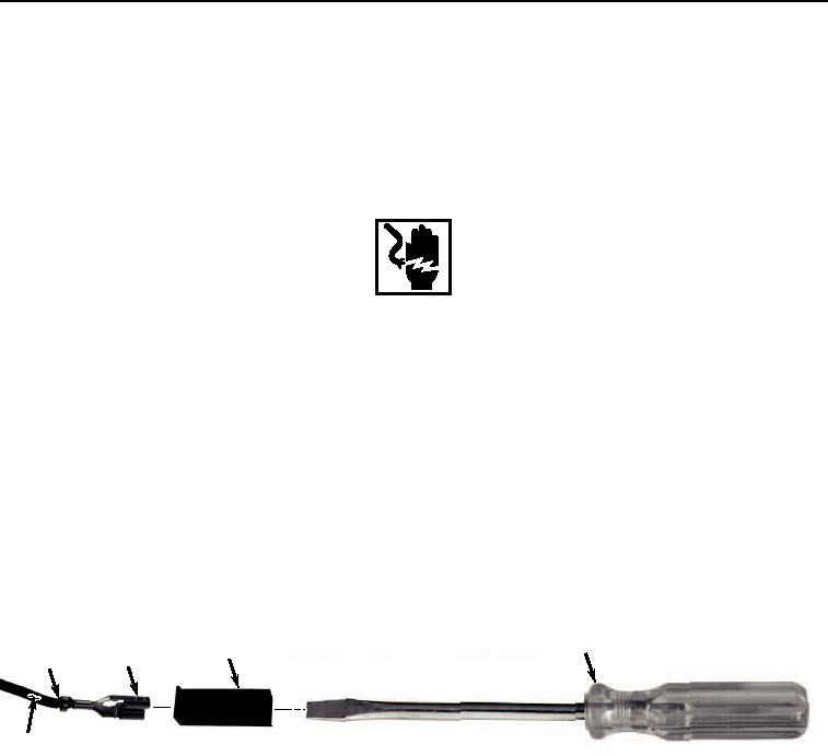
Insert screwdriver (Figure 16, Item 48) into front of connector (Figure 16, Item 49).
48
49
51
52
43
50
HYEX03222
Figure 16.
Blade Style Connector Repair.
2.
Remove screwdriver (Figure 16, Item 48) and pull wire (Figure 16, Item 50) and terminal (Figure 16, Item 51)
from the rear of connector (Figure 16, Item 49) at the same time.
3.
Cut and remove terminal (Figure 16, Item 51) from wire (Figure 16, Item 50).
4.
Remove 1/4 in. (6 mm) of insulation (Figure 16, Item 52) from end of wire (Figure 16, Item 50).
NOTE
Ensure all strands of wire are inside terminal when installing.
5.
Install wire (Figure 16, Item 50) to terminal (Figure 16, Item 51) and crimp.