
TM 5-3805-294-23-4
0512
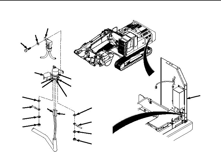
REMOVAL - Continued
3
2
1
10
4
20
15
9
5
19
7
14
8
18
6
17
13
16
12
11
HYEX00744
Figure 1. Glow Plug Relay Removal.
2.
Disconnect engine interface wiring harness connector (Figure 1, Item 6) from glow plug relay terminal (Figure
1, Item 7).
3.
Disconnect engine interface wiring harness connector (Figure 1, Item 8) from glow plug relay terminal (Figure
1, Item 9).
4.
Open cover (Figure 1, Item 10) on glow plug relay (Figure 1, Item 4).
5.
Remove nut (Figure 1, Item 11), lockwasher (Figure 1, Item 12), engine interface wiring harness connector
(Figure 1, Item 13), and washer (Figure 1, Item 14) from glow plug relay terminal (Figure 1, Item 15). Discard
lockwasher.
6.
Remove nut (Figure 1, Item 16), lockwasher (Figure 1, Item 17), fuse wiring harness connector (Figure 1, Item
18), and washer (Figure 1, Item 19) from glow plug relay terminal (Figure 1, Item 20). Discard lockwasher.
END OF TASK
INSTALLATION
1.
Install fuse wiring harness connector (Figure 2, Item 18) to glow plug relay terminal (Figure 2, Item 20) with
washer (Figure 2, Item 19), lockwasher (Figure 2, Item 17), and nut (Figure 2, Item 16).