
TM 5-3805-294-23-4
0518
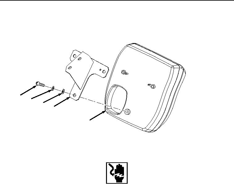
INSTALLATION
1.
Install bracket (Figure 6, Item 15) to monitor (Figure 6, Item 17) with three washers (Figure 6, Item 23),
lockwashers (Figure 6, Item 22), and screws (Figure 6, Item 21).
21
22
23
15
17
HYEX00281
Figure 6.
Bracket Installation.
WARNING
Ensure electrical power is off prior to working on all electrical connections. Prior to working
on or around vehicle, remove all jewelry, such as rings, ID tags, bracelets, etc. Jewelry, and
tools can catch on equipment, contact positive electrical circuits, and cause a direct short,
severe burns, or electrical shock. Failure to comply may result in injury or death to personnel.
2.
Position monitor (Figure 7, Item 17) to front of cover (Figure 7, Item 2) and connect monitor controller wiring
harness W3 connectors X21 (Figure 7, Item 20), X20 (Figure 7, Item 19), and X19 (Figure 7, Item 18) to monitor
(Figure 7, Item 17).