
TM 5-3805-294-23-4
0518
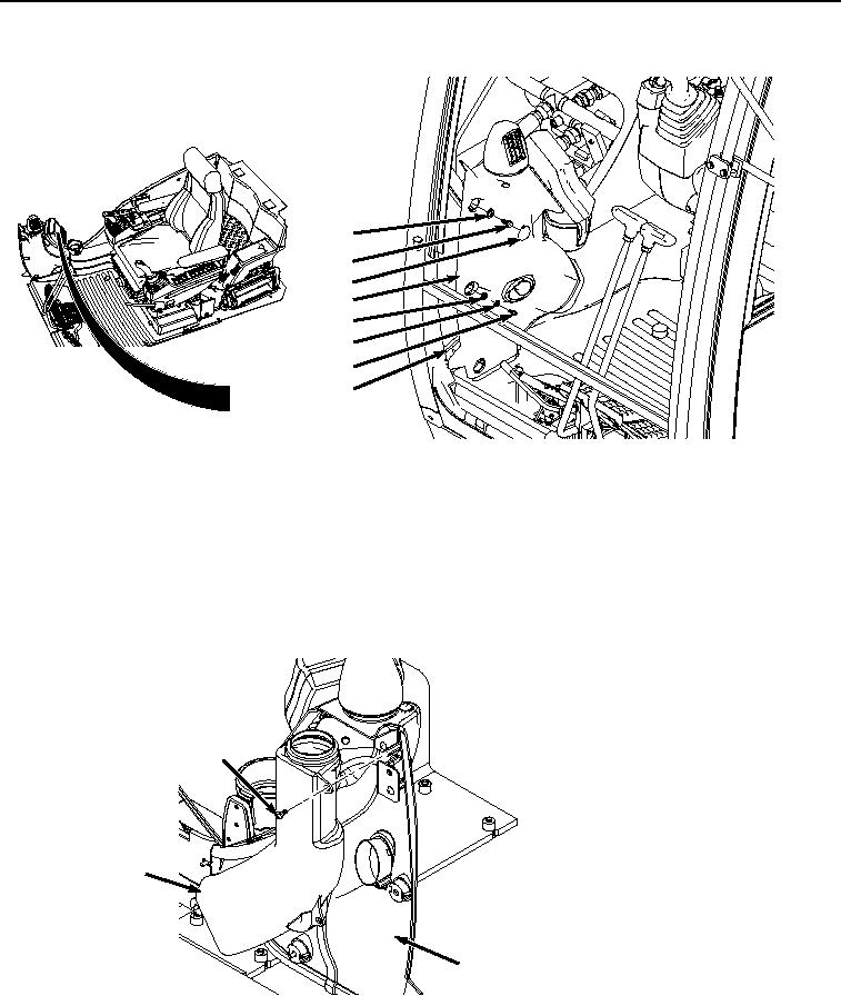
REMOVAL - Continued
4
3
1
2
8
7
6
5
HYEX00274
Figure 1. Monitor Cover Removal.
2.
Remove two bolts (Figure 1, Item 3) and washers (Figure 1, Item 4) from cover (Figure 1, Item 2) and frame
(Figure 1, Item 5).
3.
Remove two bolts (Figure 1, Item 6), lockwashers (Figure 1, Item 7), and washers (Figure 1, Item 8) from frame
(Figure 1, Item 5). Discard lockwashers.
4.
Rotate cover (Figure 1, Item 2) out and away from the frame (Figure 1, Item 5).
5.
Remove two screws (Figure 2, Item 9) and air duct (Figure 2, Item 10) from cover (Figure 2, Item 2).
9
10
2
HYEX00276
Figure 2. Air Duct Removal.
6.
Remove two screws (Figure 3, Item 11), lockwashers (Figure 3, Item 12), and washers (Figure 3, Item 13) from
brackets (Figure 3, Item 14) and (Figure 3, Item 15). Discard lockwashers.