
TM 5-3805-294-23-4
0517
REMOVAL - Continued
5
4
3
1
2
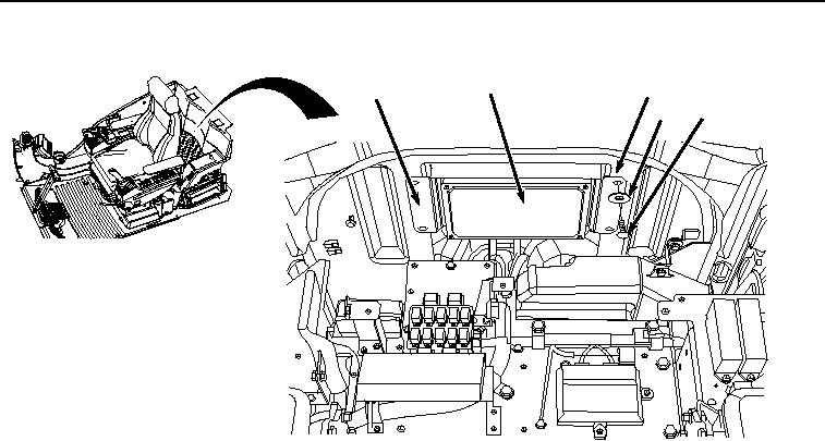
HYEX00320
Figure 1. Bracket and Main Controller Removal.
2.
Remove bracket (Figure 1, Item 3) and main controller (Figure 1, Item 5) from frame (Figure 1, Item 4).
3.
Disconnect cab wiring harness W1 connector X28 (Figure 2, Item 6) from main controller (Figure 2, Item 5).