
TM 5-3805-294-23-4
0518
INSTALLATION - Continued
17
2
19
18
20
HYEX00280
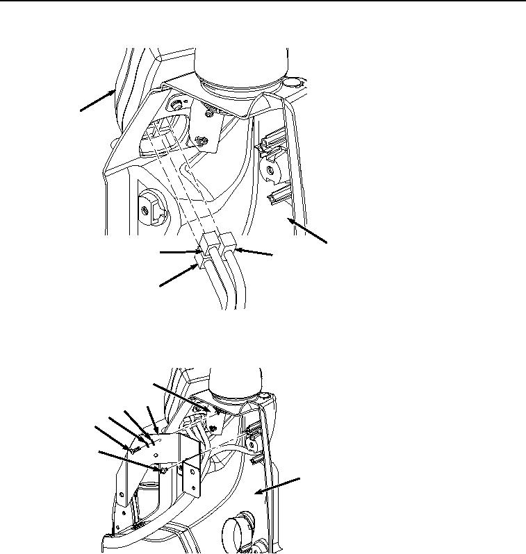
Figure 7. Monitor Installation.
3.
Install bracket (Figure 8, Item 14) to cover (Figure 8, Item 2) with two screws (Figure 8, Item 16).
15
14
13
12
11
16
2
HYEX00279
Figure 8.
Bracket Installation.
4.
Install bracket (Figure 8, Item 14) to bracket (Figure 8, Item 15) with two washers (Figure 8, Item 13),
lockwashers (Figure 8, Item 12), and screws (Figure 8, Item 11).
5.
Install air duct (Figure 9, Item 10) to cover (Figure 9, Item 2) with two screws (Figure 9, Item 9).