
TM 5-3805-294-23-4
0518
INSTALLATION - Continued
9
10
2
HYEX00276
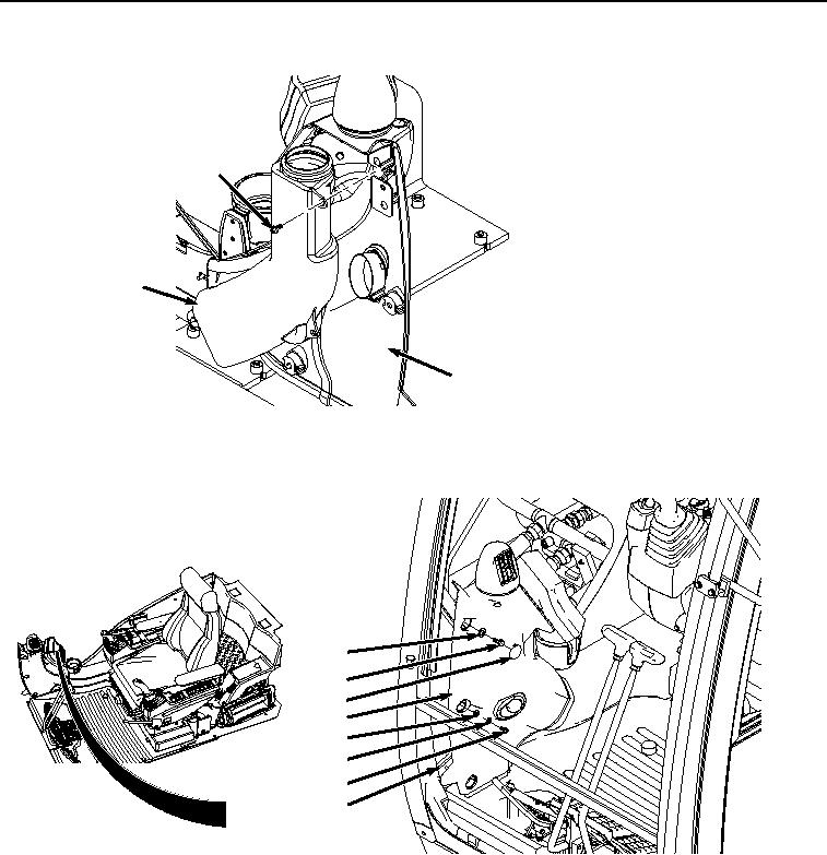
Figure 9. Air Duct Installation.
6.
Rotate cover (Figure 10, Item 2) around and toward frame (Figure 10, Item 5).
4
3
1
2
8
7
6
5
HYEX00274
Figure 10.
Monitor Cover Installation.
7.
Install cover (Figure 10, Item 2) to frame (Figure 10, Item 5) with two washers (Figure 10, Item 8), lockwashers
(Figure 10, Item 7), and bolts (Figure 10, Item 6).
8.
Install two washers (Figure 10, Item 4) and bolts (Figure 10, Item 3) to cover (Figure 10, Item 2) and frame
(Figure 10, Item 5).
9.
Install four caps (Figure 10, Item 1) to cover (Figure 10, Item 2).
END OF TASK