
TM 5-3805-294-23-4
0519
REMOVAL - Continued
34 31 33
32
30
29
28
35
27 26 25 23
5
24
HYEX00288
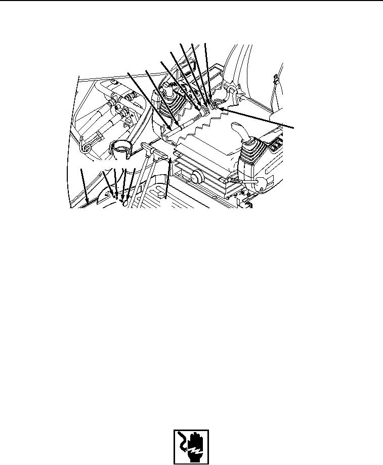
Figure 5. Cover Removal.
11.
Remove three screws (Figure 5, Item 25), lockwashers (Figure 5, Item 26), washers (Figure 5, Item 27), and
cover (Figure 5, Item 24) from frame (Figure 5, Item 5). Discard lockwashers.
12.
Remove monitor controller wiring harness W3 (Figure 5, Item 28) from clip (Figure 5, Item 29).
NOTE
Cab wiring harness W1 connections are located below and to the rear of the right-hand
console.
13.
Disconnect monitor controller wiring harness W3 connector (Figure 5, Item 30) from cab wiring harness W1
connector X22 (Figure 5, Item 31).
14.
Disconnect monitor controller wiring harness W3 connector (Figure 5, Item 32) from cab wiring harness W1
connector X23 (Figure 5, Item 33).
15.
Disconnect monitor controller wiring harness W3 connector (Figure 5, Item 34) from cab wiring harness W1
connector X24 (Figure 5, Item 35).
END OF TASK
INSTALLATION
WARNING
Ensure electrical power is off prior to working on all electrical connections. Prior to working
on or around vehicle, remove all jewelry, such as rings, ID tags, bracelets, etc. Jewelry, and
tools can catch on equipment, contact positive electrical circuits, and cause a direct short,
severe burns, or electrical shock. Failure to comply may result in injury or death to personnel.