
TM 5-3805-294-23-4
0519
INSTALLATION - Continued
17
22
2
21
19
18
20
HYEX00287
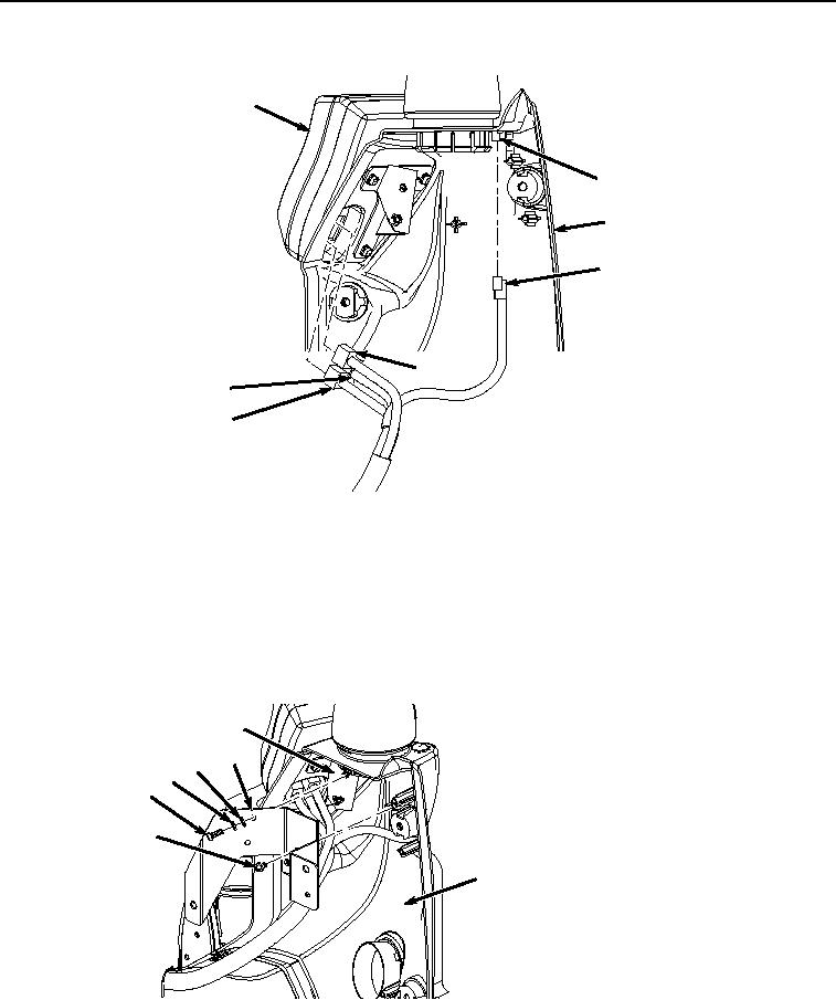
Figure 7. Monitor Installation.
8.
Connect monitor controller wiring harness W3 connector B21 (Figure 7, Item 21) to solar sensor (Figure 7,
Item 22).
9.
Position monitor (Figure 7, Item 17) to front of cover (Figure 7, Item 2) and connect monitor controller wiring
harness W3 connectors X21 (Figure 7, Item 20), X20 (Figure 7, Item 19), and X19 (Figure 7, Item 18) to monitor
(Figure 7, Item 17).
10.
Install bracket (Figure 8, Item 14) to cover (Figure 8, Item 2) with two screws (Figure 8, Item 16).
15
14
13
12
11
16
2
HYEX00286
Figure 8.
Bracket Installation.
11.
Install bracket (Figure 8, Item 14) to bracket (Figure 8, Item 15) with two washers (Figure 8, Item 13),
lockwashers (Figure 8, Item 12) and screws (Figure 8, Item 11).