
TM 5-3805-294-23-4
0538
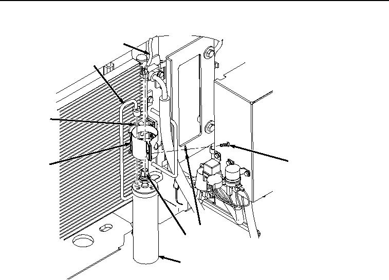
INSTALLATION - Continued
9
8
14
11
13
12
10
5
HYEX00314
Figure 5. Receiver-Dryer Installation.
3.
Install O-ring (Figure 5, Item 14) to line (Figure 5, Item 8).
4.
Position receiver-dryer (Figure 5, Item 5) on line (Figure 5, Item 8) with O-ring (Figure 5, Item 14) and install
to bracket (Figure 5, Item 13) with washer (Figure 5, Item 12) and bolt (Figure 5, Item 11).
5.
Install connector B20 (Figure 5, Item 9) to switch (Figure 5, Item 10).
6.
Install bolt (6) and washer (Figure 6, Item 7) to line (Figure 6, Item 8) and receiver-dryer (Figure 6, Item 5).