
TM 5-3805-294-23-4
0538
REMOVAL - Continued
9
8
14
11
13
12
10
5
HYEX00314
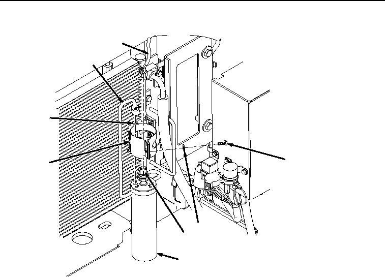
Figure 2.
Receiver-Dryer Removal.
5.
Remove bolt (Figure 2, Item 11) and washer (Figure 2, Item 12) from bracket (Figure 2, Item 13).
CAUTION
Ensure line (8) is held in place when receiver-dryer is removed. Line is easily moved and can
be kinked if receiver-dryer is pulled away without supporting line. Failure to comply may result
in damage to equipment.
6.
Remove receiver-dryer (Figure 2, Item 5) from line (Figure 2, Item 8) and bracket (Figure 2, Item 13).
7.
Remove O-ring (Figure 2, Item 14) from line (Figure 2, Item 8). Discard O-ring.
8.
Remove two bolts (Figure 3, Item 15) and bracket (Figure 3, Item 13) from condenser (Figure 3, Item 16).