
TM 5-3805-294-23-4
0539
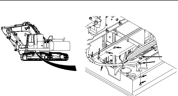
REMOVAL - Continued
8
6
9
7
13
12
3
11
10
HYEX00532
Figure 2. Clamps Removal.
4.
Remove clamp (Figure 2, Item 8) from hose (Figure 2, Item 3).
5.
Remove bolt (Figure 2, Item 10), washer (Figure 2, Item 11), hose (Figure 2, Item 3), and clamp (Figure 2,
Item 12) from bracket (Figure 2, Item 13).
6.
Remove clamp (Figure 2, Item 12) from hose (Figure 2, Item 3).
7.
Remove two bolts (Figure 3, Item 14) and washers (Figure 3, Item 15) from cover (Figure 3, Item 16) and floor
(Figure 3, Item 17).