
TM 5-3805-294-23-4
0539
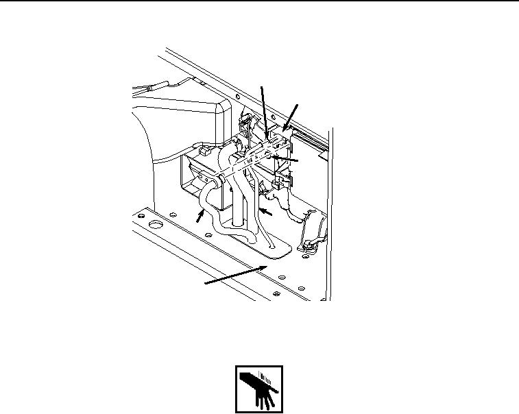
INSTALLATION - Continued
28
26
27
3
23
17
HYEX00516
Figure 7.
Hose Installation.
WARNING
2.
Lightly lubricate O-ring (Figure 7, Item 28) with clean refrigerant oil.
3.
Install O-ring (Figure 7, Item 28) to hose (Figure 7, Item 3).
4.
Install hose (Figure 7, Item 3) and O-ring (Figure 7, Item 28) to evaporator (Figure 7, Item 26).
5.
Lightly lubricate O-ring (Figure 7, Item 27) with clean refrigerant oil.
6.
Install O-ring (Figure 7, Item 27) to hose (Figure 7, Item 23).
7.
Install hose (Figure 7, Item 23) and O-ring (Figure 7, Item 27) to evaporator (Figure 7, Item 26).
8.
Install bolt (Figure 8, Item 24) and washer (Figure 8, Item 25) to hose (Figure 8, Item 23) and evaporator (Figure
8, Item 26).