
TM 5-3805-294-23-4
0539
INSTALLATION - Continued
13.
Install clamp (Figure 11, Item 8) to hose (Figure 11, Item 3) and bracket (Figure 11, Item 9) with bolt (Figure
11, Item 6) and washer (Figure 11, Item 7).
14.
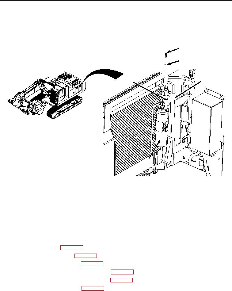
Lightly lubricate O-ring (Figure 12, Item 4) with clean refrigerant oil.
1
2
3
4
5
HYEX00524
Figure 12.
Receiver-Dryer Hose Installation.
15.
Install O-ring (Figure 12, Item 4) to hose (Figure 12, Item 3).
16.
Install hose (Figure 12, Item 3) and O-ring (Figure 12, Item 4) to receiver-dryer (Figure 12, Item 5) with bolt
(Figure 12, Item 1) and washer (Figure 12, Item 2).
END OF TASK
FOLLOW-ON MAINTENANCE
1.
Replace receiver-dryer. (WP 0538)
2.
Install cab rear tray and cover. (WP 0566)
3.
Install cab rear lower armor plate. (WP 0588)
4.
Install storage compartment lower access cover. (WP 0610)
5.
Install cooling compartment lower access cover. (WP 0591)
6.
Service air conditioner refrigerant. (WP 0540)