• Home
  • Download PDF
  • Order CD-ROM
  • Order in Print
Figure 3. Servo Motor Removal.
Figure 6. Wiring Harness Installation

Maintenance Manual For Hydraulic Excavator Type 1 With Hydraulic Thumb And Quick Latch -4 Page Navigation
  434    435    436    437    438  439  440    441    442    443    444  
img
.
TM 5-3805-294-23-4
0548
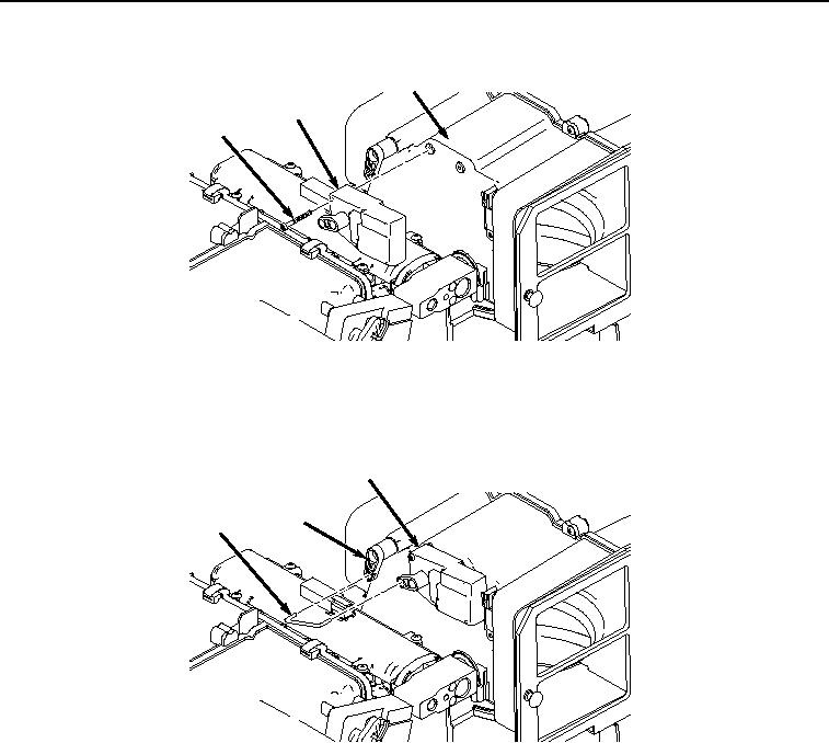
INSTALLATION - Continued
6
2
5
HYEX02169
Figure 4. Servo Motor Installation.
2.
Install rod (Figure 5, Item 3) to servo motor (Figure 5, Item 2) and lever (Figure 5, Item 4).
2
4
3
HYEX02168
Figure 5. Rod Installation.
3.
Install right-hand console wiring harness W11 connector M9 (Figure 6, Item 1) to servo motor (Figure 6, Item
2).
0548-4


Privacy Statement
Press Release
Contact

© Copyright Integrated Publishing, Inc.. All Rights Reserved.