
TM 5-3805-294-23-4
0551
INSTALLATION - Continued
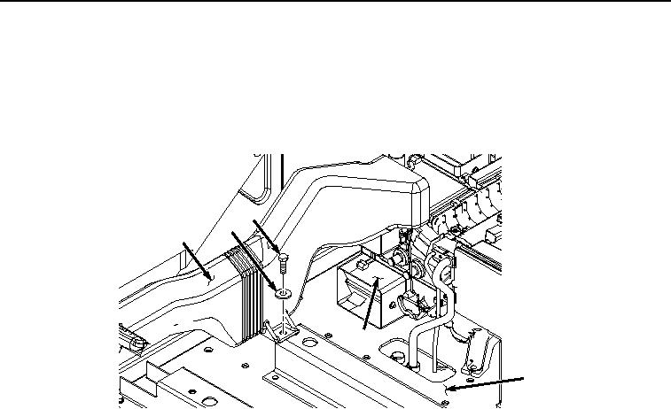
NOTE
Seat stand shown removed for clarity.
4.
Install air conditioner/heater duct (Figure 13, Item 44) to cab (Figure 13, Item 41) and air conditioner/heater
unit (Figure 13, Item 45) with screw (Figure 13, Item 42) and washer (Figure 13, Item 43).
42
43
44
45
41
HYEX02534
Figure 13.
Duct Installation.
5.
Install cover (Figure 14, Item 37) to cab (Figure 14, Item 41) with three screws (Figure 14, Item 38), lockwashers
(Figure 14, Item 39), and washers (Figure 14, Item 40).