
TM 5-3805-294-23-4
0551
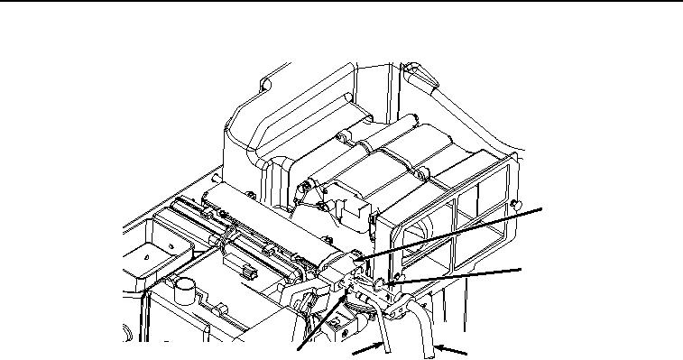
INSTALLATION - Continued
33
34
29
35
30
HYEX02532
Figure 15.
Air conditioner Hose Installation.
8.
Install O-ring (Figure 15, Item 35) to hose (Figure 15, Item 30).
9.
Lightly lubricate O-ring (Figure 15, Item 34) with clean oil.
10.
Install O-ring (Figure 15, Item 34) to hose (Figure 15, Item 29).
11.
Install hose (Figure 15, Item 30) and O-ring (Figure 15, Item 35) to expansion valve (Figure 15, Item 33).
12.
Install hose (Figure 15, Item 29) and O-ring (Figure 15, Item 34) to expansion valve (Figure 15, Item 33).
13.
Install screw (Figure 16, Item 31) and washer (Figure 16, Item 32) to hose (Figure 16, Item 29) and expansion
valve (Figure 16, Item 33).