
TM 5-3805-294-23-4
0551
INSTALLATION - Continued
30
33
29
32
31
28
27
HYEX02531
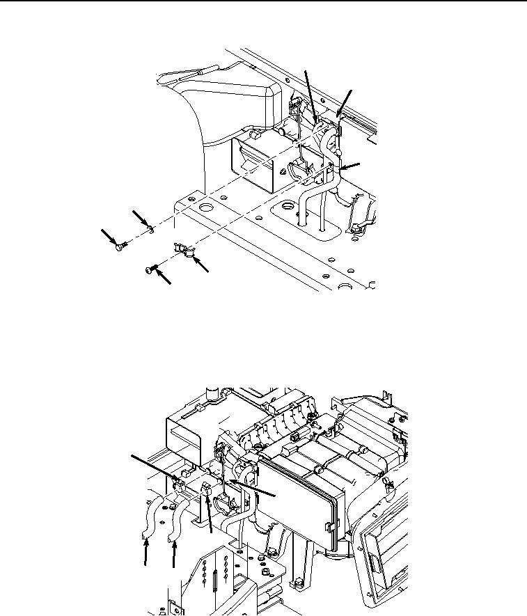
Figure 16. Expansion Valve Screw Installation.
14.
Install screw (Figure 16, Item 27) and clamp (Figure 16, Item 28) to hose (Figure 16, Item 29) and hose (Figure
16, Item 30).
15.
Install hose (Figure 17, Item 26) and hose clamp (Figure 17, Item 25) to heater core (Figure 17, Item 24).
25
24
22
26
23
HYEX02530
Figure 17.
Heater Hose Installation.
16.
Install hose (Figure 17, Item 23) and hose clamp (Figure 17, Item 22) to heater core (Figure 17, Item 24).
17.
Open heater valve (Figure 18, Item 21) at engine (Figure 18, Item 20).