
TM 5-3805-294-23-4
0560
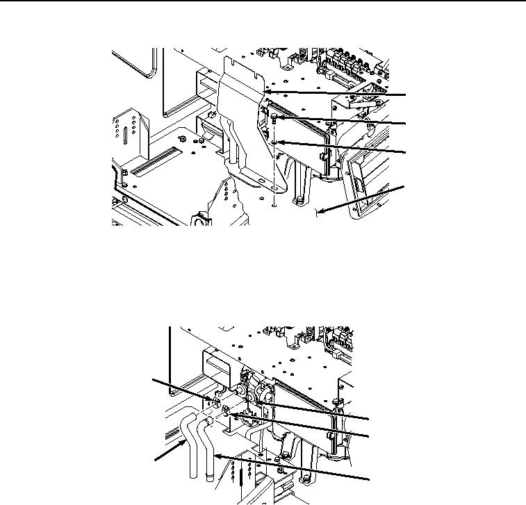
REMOVAL - Continued
5
6
7
8
HYEX01924
Figure 3.
Bolts and Cover Removal.
NOTE
Position drain pan under cab prior to removing heater hoses.
4.
Remove hose clamp (Figure 4, Item 9) and hose (Figure 4, Item 10) from heater core (Figure 4, Item 11).
9
11
12
10
13
HYEX01927
Figure 4.
Hose Removal.
5.
Remove hose clamp (Figure 4, Item 12) and hose (Figure 4, Item 13) from heater core (Figure 4, Item 11).
6.
Remove rod (Figure 5, Item 14) from servo motor (Figure 5, Item 15).