
TM 5-3805-294-23-4
0560
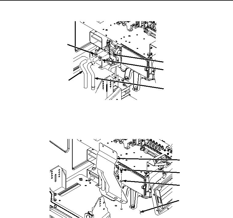
INSTALLATION - Continued
9
11
12
10
13
HYEX01927
Figure 9. Hose Installation.
4.
Install hose clamp (Figure 9, Item 9) and hose (Figure 9, Item 10) to heater core (Figure 9, Item 11).
5.
Install cover (Figure 10, Item 5) to cab (Figure 10, Item 8) with two bolts (Figure 10, Item 6) and washers (Figure
10, Item 7).
5
6
7
8
HYEX01924
Figure 10.
Bolts and Cover Installation.
6.
Install bolt (Figure 11, Item 3) and washer (Figure 11, Item 4) to cover (Figure 11, Item 5).