
TM 5-3805-294-23-4
0567
REMOVAL - Continued
14.
Remove two bolts (Figure 5, Item 34), washers (Figure 5, Item 35), and left side bracket (Figure 5, Item 33)
from cab (Figure 5, Item 9).
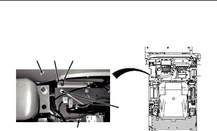
15.
Remove two bolts (Figure 6, Item 36) and washers (Figure 6, Item 37) from electrical panel (Figure 6, Item 29)
and right side bracket (Figure 6, Item 38).
9
38
39, 40
36, 37
29
HYEX02825
Figure 6. Right Side Bracket Removal.
16.
Remove two bolts (Figure 6, Item 39), washers (Figure 6, Item 40), and right side bracket (Figure 6, Item 38)
from cab (Figure 6, Item 9).
17.
Remove four bolts (Figure 7, Item 41), washers (Figure 7, Item 42), and main controller assembly (Figure 7,
Item 43) from cab (Figure 7, Item 9).